Overview
A 2D/3D mapping/scanning project consisting off:
- robot side code
- cross-platform visualization
Robot side code is really a bunch of super-simple programs which I call modules. Each of those programs works perfectly well from the command line without the rest of the project. The sole exception is ev3control module which enables/disables/monitors other modules. The repository for robot side code is ev3dev-mapping-modules.
The cross-platform visualization is a Unity project that can plot the readings in real-time and/or control the robot. Like other projects written in Unity it works on more than 10 platforms, in theory at least. Unity has also a nice abstraction for input so robots can be controlled with keyboards/pads/mice/wheels/mobiles and so on. The repository for cross-platform visualization is ev3dev-mapping-ui.
I try to keep the budget of the project low, around 400$ (360€) including EV3 and motors.
The meta-repository of the project is ev3dev-mapping.
This is my personal project. While I am quite happy to share the results, please keep in mind that I am pursuing my own goals here.
Examples
The 3D examples are X3D models.
You can interact with the scenes with your mouse and keyboard:
- rotation with LMB
- rotation point selection with double LMB
- pan with ctrl key + LMB
- zoom with the wheel or alt + LMB or RMB
- reset the view with r key
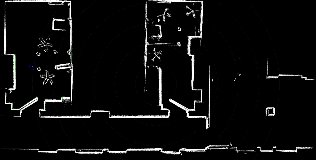
Example Phase II raw scan
Example Phase II result + MeshLab surface reconstruction
The technology behind the X3D models on this page is X3DOM. See X3DOM supported browsers if you are interested.
Phase I
Goals:
- Hardware selection
- CruizCore XG1300L gyroscope for low bias drift and great accuracy
- XV11 Lidar for unmatched… price
- Drivers
- CruizCore XG1300L driver on top of wonderful @dlech sensor driver framework
- XV11 Lidar in userspace using extensive information from xv11hacking
- Correct geometry
- nobody (on the internet) seems to treat XV11 rotational geometry correctly
- LIDAR standard deviation
- evaluation with respect to distance
- Experimental 2D mapping
- experimental code to learn and throw away
The Phase I is finished with results:
- Using the XV11 Lidar tutorial
- xv11lidar C/C++ library
- mi-xg1300l CruizCore XG1300L driver
- ev3dev-mapping-abandoned repository
The Phase I robot in action:
- How to interface XV11 LIDAR to EV3 using ev3dev
- EV3 Gyro vs CruizCore XG1300L vs Odometry - Position Estimation
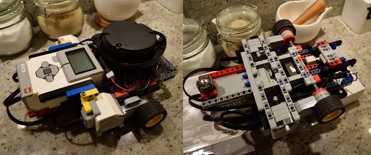
 Hardware used for testing in Phase I
Phase II
Goals:
- Cross-platform visualisation/computation/control
- Modular architecture design
- modules as simple command line programs in any language
- supervisor on top that does ‘magic’
- UI components counterpart of modules
- 3D mapping with lidars in arbitrary position/rotation
- XY and XZ plane support with any position, generalizing is easy
- Mapping in movement
- precise per reading interpolation for position/heading
- Support for hundreds of thousands of points on average laptop
- lidar spits around 100k points a minute!
- Network communication recording/replaying
- for running same data with different algorithms/parameters added features
- for reprocessing the data on more powerful machine if needed
- for near-perfect path repeating
- Data export to widely-accepted file format
- ply chosen for ease of implementation
- Multiple lidars support at the same time
- just use multiple Laser components
- Multiple robots support at the same time
- no problem but drive (keyboard, pad) scripted for single robot now
- Extensibility for different hardware
- this needs writing own modules/components
Phase II is functionally finished now with results:
- ev3dev-mapping-ui Unity project repository
- ev3dev-mapping-modules robot modules repository
- ev3dev-mapping-ui-udp recorded UDP communication from some mappings
- ev3dev-mapping-results with screenshots/3D models/pipelines
The Phase II robot in action:
State of the Project
Information from 10 Aug. 2016.
Phase II is functionally finished. I am tidying up the code. It will take some time:
- ev3control & Control are rewritten for TCP/IP, UDP is working but not suitable for that
- Unity component model is reworked from flat structure to hierarchical structure (robot with child subsystems instead of with all components)
- common properties are moved to separate components (e.g. Network Configuration component)
- component dependencies are reworked (e.g. Laser, LaserRenderer, LaserUI components instead of Laser with nested renderer, and ui prefabs)
- UI needs some work but I am rather leaning towards built-in console
Phase III is in plans but I need a break now.
Architecture
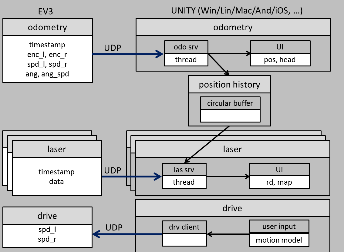
 Phase II software architecture
The odometry module sends timestamped position and heading data to the odometry component. Position and heading are reflected in the UI.
The data is kept in position history component in circular buffer.
The laser module sends timestamped data to the laser component. The laser component grabs position snapshots in required timeframe from the position history component.
The position and heading data is interpolated individually for each laser reading. Once the data is ready it is reflected in the UI.
The drive component translates input from the user (keyboard, pad, numerical, …) using the motion model and sends it to the drive module.
The drive module controls the motors.
The control component and the control module are not in the scheme for clarity. The control component sends to control module requests to enable/disable modules.
The control module replies with module states.
Building Instructions
Using the XV11 Lidar tutorial has information on electrical/mechanical XV11 Lidar interfacing.
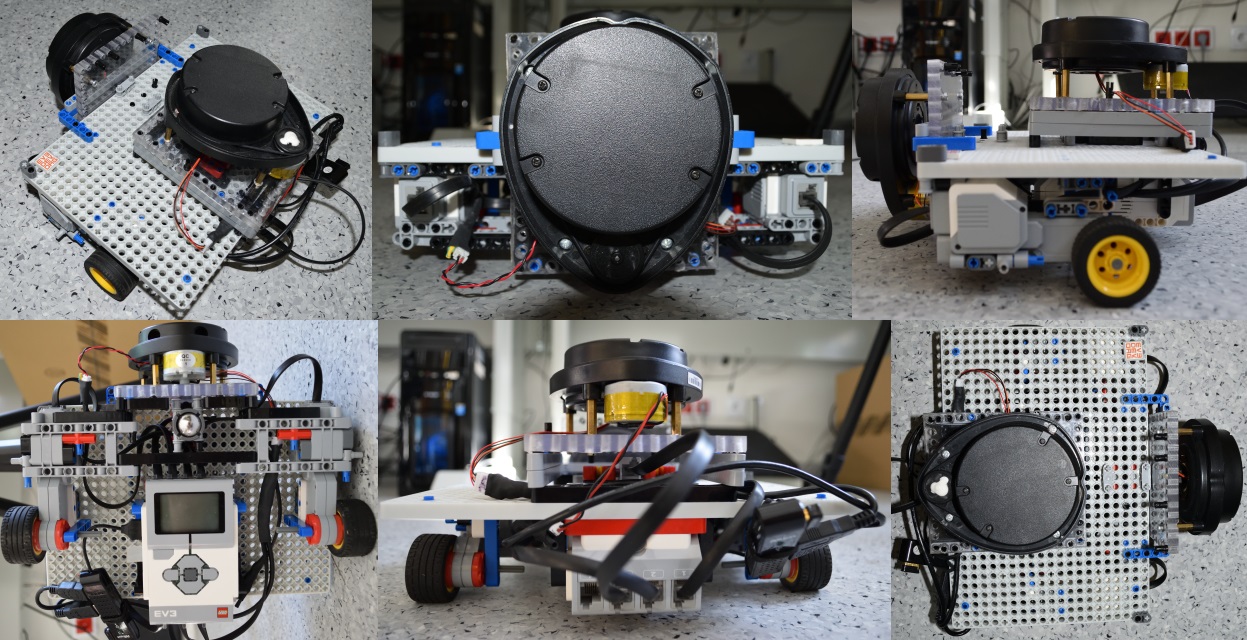
 Hardware used for testing in Phase II
Phase II key parts:
- 2 large EV3 motors (95658)
- caster wheel (99948 + 92911)
- MicroInfinity CruizCore gyroscope, see mi-xg1300l
- 2 lidars ripped off Neato, see Using the XV11 Lidar tutorial
- MinuteBot technic baseplate
One XY-plane lidar is enough for 3D scanning. The XZ-plane lidar is for orientation and Phase III project.
Working with 3D data
MeshLab is a great UI tool for post-processing point clouds exported from ev3dev-mapping-ui. Its functionality includes normals calculation, surface reconstruction and export to U3D (for 3D pdfs), X3D (for 3D on the web) and other common 3D formats.
AOPT is a great command-line tool for optimizing X3D models for the web. It is part of InstantReality virtual/augmented reality framework. One way to share X3D content on the web is using X3DOM which is supporting implementation in ongoing Web3D and W3C discussion on declarative 3D content in html.
For example pipelines used for post-processing ev3dev-mapping-ui data see ev3dev-mapping-results.
Feedback
If you have some question or problem open an issue in one of the ev3dev-mapping project repositories.
References
ev3dev-mapping
ev3dev-mapping - the project meta-repository
ev3dev-mapping-modules - the robot modules repository
ev3dev-mapping-ui - the cross platform UI repository
ev3dev-mapping-ui-udp - the recorded UDP communication repository
ev3dev-mapping-results - the results with explained pipelines repository
drivers and libraries
xv11lidar - C/C++ library repository
mi-xg1300l - CruizCore XG1300L driver documentation
X3DOM - open-source framework for declarative 3D graphics on the Web
tutorials and learning
Using the XV11 Lidar tutorial - the lidar integration with EV3
xv11hacking - the xv11hacking page
videos
How to interface XV11 LIDAR to EV3 using ev3dev - video on interfacing the lidar
EV3 Gyro vs CruizCore XG1300L vs Odometry - Position Estimation - video on position estimation
3D mapping/scanning project with ev3dev OS and Unity UI - phase II robot in action
tools
Unity - the Unity engine
MeshLab - open source system for the processing of 3D meshes
AOPT - command line tool for creating optimized X3DOM content, part of InstantReality
InstantReality - framework for Virtual Reality (VR) and Augmented Reality (AR)
file formats and standards
X3D - ISO standard for 3D content suitable for the web
U3D - Ecma standard for 3D content supported natively by pdf format
Web3D - is organization behind X3D spreading 3D web content
WebGL - cross-platform web standard for a low-level 3D graphics API
W3C - the main organization behind World Wide Web standards
Project Info
-
Written with
C/C++/C#/HLSL
- Project homepage
- Source code
-
